MixSID
flexible stereo SID board with integrated channel mixer
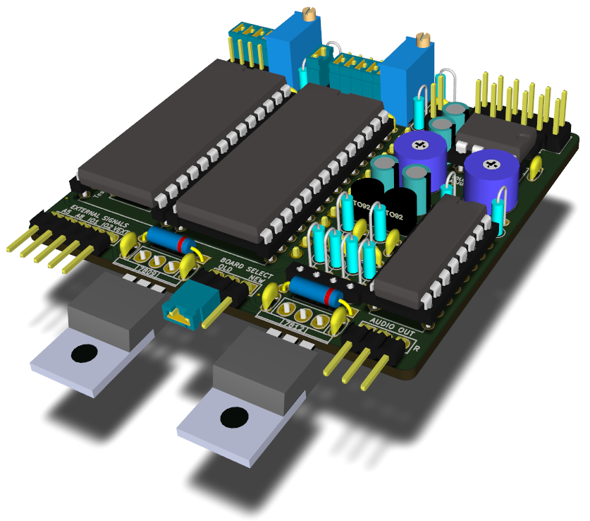
The MixSID is a stereo SID board for the C64 that can be used with any combination of SID models on a wide range of C64 mainboards.
Features include an integrated stereo channel mixer, pragmatic stereo addressing scheme, flexible handling of io areas, onboard audio input, output and digiboost circuits, dedicated stereo output, full paddle compatibility and versatile digital control.
 For a quick overview of available features, hardware configuration
options and the effects of the runtime control signals, please see the
interactive configuration
tool.
For a quick overview of available features, hardware configuration
options and the effects of the runtime control signals, please see the
interactive configuration
tool.
 Easy step-by-step build
instructions are provided to help with populating the board. For
each step the required components, their locations and values are
shown in detail.
Easy step-by-step build
instructions are provided to help with populating the board. For
each step the required components, their locations and values are
shown in detail.
Documentation is available in both english and german.
Features
The board fits on the most common C64 mainboard models, namely 250407, 250425, 250466 (breadbox) and 250469 (flat case).
It probably won't fit on the early 326298 and KU14194HB models, it does fit into an SX64 but will need some sdjustments.
The board and component dimensions were carefully chosen to allow installation in either flat or breadbox type C64 cases.
Both +12V and +9V can be generated directly on the board, making the choice of SID models independent from the C64 mainboard.
On older mainboards, the +12V provided at the SID socket are used to generate the +9V for the 8580. On the later 250469 mainboard both voltages are generated from the +20V available at the cathode lead of CR3.
Jumpers are used to configure the SID model and mainboard type, making it easy to use the same build on different mainboards and with different SIDs. There is no need to settle for a specific setup at build time.
The integrated channel mixer controls which SID output appears on which stereo output channel. Listen to a single SID in mono, or listen to both SIDs in stereo.
Four different mixer settings are available:
- SID1 on both channels (mono)
- SID2 on both channels (mono)
- SID1 on left channel, SID2 on right channel (stereo)
- SID1 on right channel, SID2 on left channel (stereo)
There are only two major modes controlling the address of the second SID.
In parallel mode, both SIDs appear the standard address range starting at $D400. When a mono tune is played, both SIDs will play the same.
In stereo mode, the secondary SID listens on all addresses which are commonly used by stereo tunes at the same time, namely on $D420 and $D500, and optionally also on $DE00 and/or $DF00.
This frees the user from having to care for the specific stereo address expected by a certain stereo tune. All that is necessary is to switch to stereo mode.
It is possible to virtually swap the roles of the SIDs in terms of addressing for stereo tunes, i.e. to control which SID should stay at $D400 (primary) and which SID should move to the stereo addresses (secondary).
Stereo tunes written for a mix of SID models may expect either model as the primary SID, so this feature makes it possible to listen to these tunes as intended, without having to physically swap SIDs in their sockets.
You can control which SID responds to read requests even if both SIDs are addressed in parallel at $D400. Only the primary SID will thus respond SID detection attempts by software.
The user may permanently connect the I/O1 and I/O2 lines from the C64 mainboard and still control at runtime whether or not the secondary SID should actually appear at the corresponding addresses $DE00 and/or $DF00 when in stereo addressing mode.
This makes it trivial to avoid conflicts with expansion port modules using the same address ranges.
Paddles and mice just work regardless of the current runtime configuration.
When addressed in parallel at $D400, only the primary SID will respond to read requests, while the secondary SID is forced write-only.
In addition, the POTX and POTY lines are multiplexed to whichever SID is currently configured as the primary SID, so that switching SID priority won't affect paddle function either.
For each SID a dedicated output circuit is integrated on board to achieve independence from the variant used on the current C64 mainboard. The output circuits are identical to the circuit used on the 250469 model, with variations for different SID models (R8) taken into account. Both output signals will end up at a dedicated stereo output after mixing.
The board includes all circuity necessary to either boost the 8580 sample volume, use audio-in features of the SIDs or reduce noise by grounding audio-in.
Since different models and SID chips may produce different output levels, the board includes individual volume adjustment pots for each SID.
It is also possible to additionally route the audio output to the existing output circuit on the mainboard, so that sound will also end up at the A/V connector and as part of the composite signal. The user may either settle on one of the two SIDs or decide to mix down both signals to mono (although the latter option will introduce some crosstalk).
Apart from the power supply and model settings, all runtime features are optional, and sensible settings are used as defaults.
For example, if no other external or control signals are connected, the second sid is addressed in parallel to the first, and both appear on separate stereo channels by default.
If the user wishes to listen to some stereo tunes, A5 and A8 need to be connected, and the MODE SELECT control signal (MS) can be used to switch between addressing modes.
If the user wishes to listen to the individual SID outputs as well, the M0 and M1 signals can be used to control the channel mixer, and so on.
All runtime features are controlled by 5V logic signals. These signals are driven high when not connected, so they can be controlled by either leaving them open or simply connecting them to ground. Thus simple jumpers or switches can be used as well as external logic signals.
This makes the MixSID suitable for simple means of control, but also allows it to be controlled by more sophisticated devices such as the keyman64.
No attempt is made to free you from the responsibility of using the proper configuration for your SID chips. You, and only you, configure the mainboard type, the supply voltage, filter caps and output circuit resistors via physical jumpers.
In order to help you take this responsibility, this project strives to deliver complete and extensive documentation.
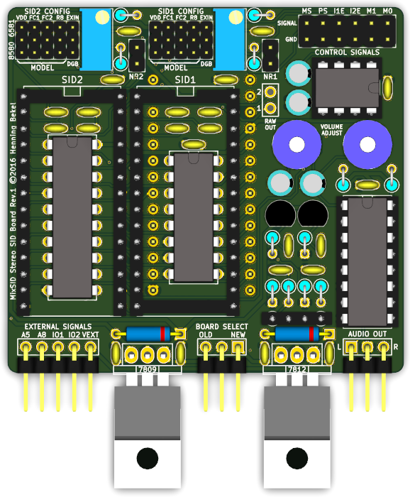
The board has been designed to be easy to produce and to be assembled by hand, using only low-tech components in through-hole packages. Gerber files are provided that can be send to any board house for production.
All source and design files are published and can be used freely under the terms of the GNU General Public License Version 2.
Documentation
- Downloads
- Ordering Assembly Kits
- Prerequisites
- Assembly
- Installation
- Configuration
- Runtime Control Signals
- Schematics
- License
Downloads
Source
The source distribution includes the source for the 16V8GAL logic as well as schematics and pcb layouts in KiCad format.
Latest stable is MixSID-1.0.tar.gz.
All releases can be found under /download/MixSID
Latest developments are available via github:
git clone https://github.com/hbekel/MixSID
Binaries
- MixSID-firmware-1.0.jed JEDEC file for the GAL16V8 (source)
- MixSID-r1-gerber.zip gerber files for revision 1 board
Ordering Assembly Kits
I’m offering assembly kits including the MixSID pcb, preprogrammed GAL and all required components (except connection cables and SID chips) for 25€ each. Worldwide shipping via regular mail is free of charge.
You can order kits via email at henning.liebenau@protonmail.com
To place an order, please include the word “MixSID” in the subject. State your full name, your complete international shipping address and the number of kits you wish to buy. Note that orders are limited to a maximum of two kits per person. You will receive an email containing payment information (bank transfer only). You will have to pay in advance to confirm your order.
Notes on availability
I try to keep a sufficent number of kits on stock, but please note that I’m doing all of this in my spare time, on a short budget and a minimal profit margin. My primary motivation is to serve the community, not to run a profitable business.
This means that in case I am currently out of stock, it may take a few weeks until I can put together a new batch of kits to fullfill your order. I may even need to collect a sufficient number of prepaid orders before I can afford to order the necessary parts myself. In these cases I will regularily inform you about the status of your order. Thus some patience and trust may be required on your part.
Prerequisites
Supported mainboards
The board has been confirmed to fit and work properly on 250407, 250425, 250466, and 250469 mainboards.
- A5 from UD1 Pin 3
- A8 from UD1 Pin 23
- IO1 from UC1 Pin 10
The board probably won’t fit on the early 326298 and KU14194HB models.
Note that the MixSID has not been tested on the latter mainboards, so your mileage may vary. If you choose to try and install on one of these, please feed back your results.
Board dimensions
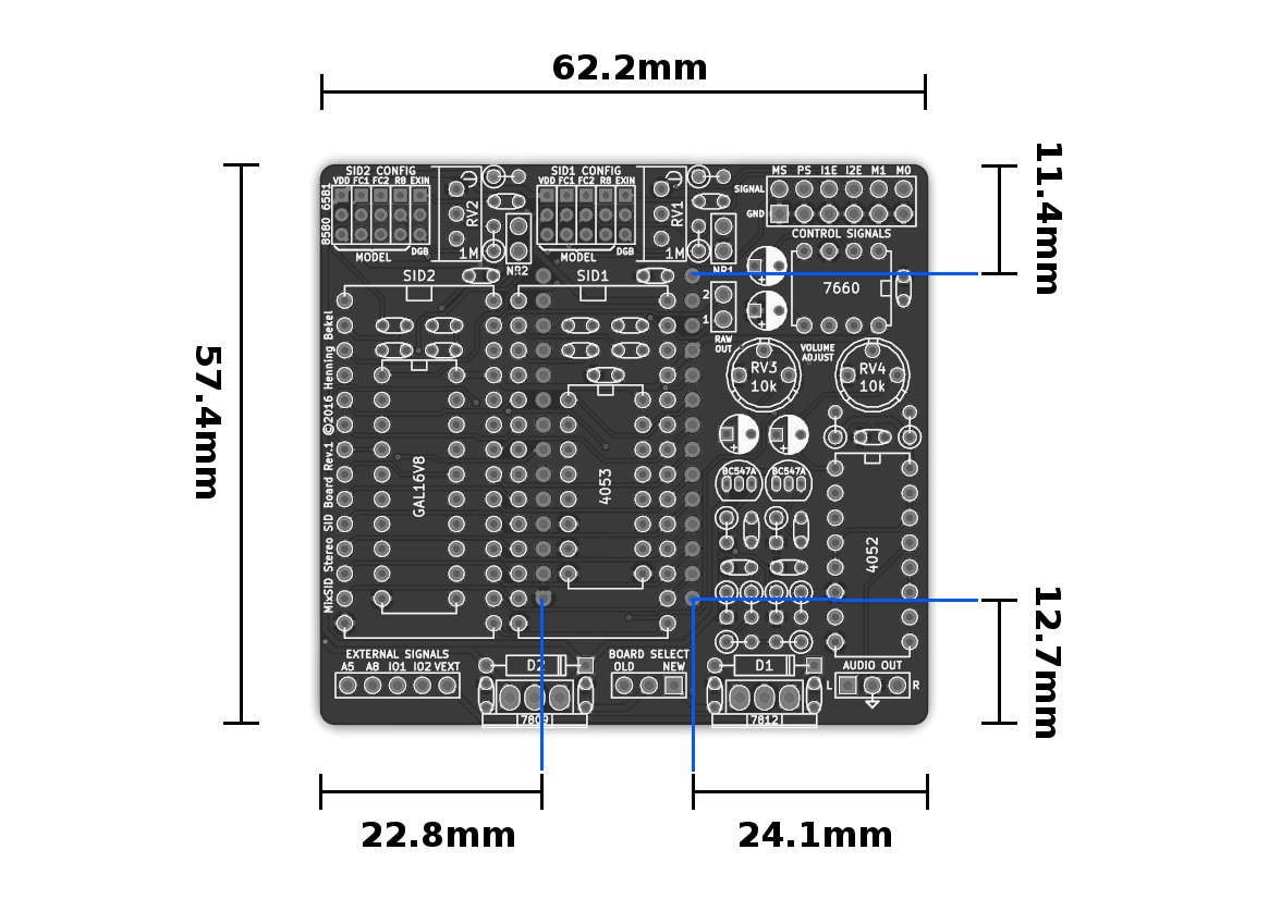
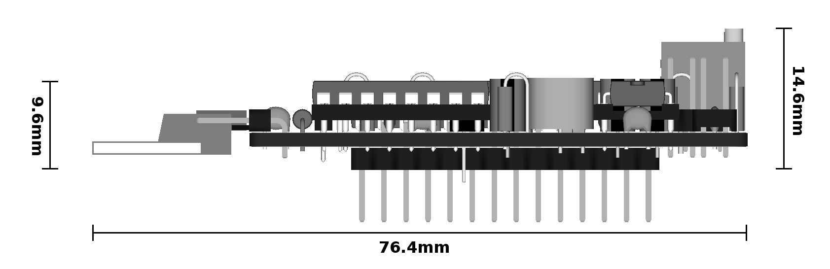
Size constraints
When installing on a mainboard on which the SID socket is located near the top edge, the MixSID board will partially hover above the CPU. If the CPU sits in a socket itself, another socket in between the SID socket and the MixSID board is required to lift it above the CPU.
If you want to use coolers for the SID chips on a board where the SID socket is located near the bottom edge of the board you won’t be able to use a flat case unless you cut a gap into the keyboard frame. This is a constraint that applies to virtually all stereo SID boards.
Pin headers
You may want to consider what kind of pin header to use for the control signals, depending on what mainboard(s) you want to install on and how you plan to control the device.
If you are planning to use jumpers or simple switches, a double row pin header may be the best choice, since the lower row conveniently supplies GND.
If you plan to interface the control signals from another logic IC or microcontroller you can opt to use a single row pin header to obtain only the control signals instead.
If you plan to exclusively install the board on a mainboard where the SID is located in the lower half of the mainboard (250407 or 250469) and in a case were height is an issue, an angled header may be the best choice. Note though that an angled header will prevent you from installing the board in a 250425 or 250466 later on since the board sits very close to the serial connector on these mainboards.
Assembly
Having carefully considered the prerequisites, assembly should be straightforward as only through-hole components are used. However, some care must be taken when soldering the components placed below the SIDs and inside the SID sockets, since soldering them in the wrong order can leave you unable to proceed.
You can therefore follow these step-by-step
instructions to avoid any pitfalls during build.
Please refer to the list of parts and component placement reference below for further information.
All resistors are 1/4W. Use metal or precision types.
Ceramic/Film Capacitors should be as small as possible.
There’s also a shopping cart (excluding the GAL16V8D) from the german supplier Reichelt for further reference.
| Amount | Type | Value | Package/RM |
|---|---|---|---|
| 1 | GAL16V8D | 15ns | DIP20 7.62mm |
| 1 | 74HC4052 | DIP16 7.62mm | |
| 1 | 74HC4053 | DIP16 7.62mm | |
| 1 | ICL7760 | DIP8 7.62mm | |
| 2 | Resistor | 100k | 6.5mm, ∅ 2.5mm |
| 2 | Resistor | 220k | 6.5mm, ∅ 2.5mm |
| 4 | Resistor | 1k | 6.5mm, ∅ 2.5mm |
| 2 | Resistor | 10k | 6.5mm, ∅ 2.5mm |
| 2 | Resistor | 4.7k | 6.5mm, ∅ 2.5mm |
| 9 | Ceramic/Film capacitor | 100nF | 2.5mm |
| 4 | Ceramic/Film capacitor | 22nF | 2.5mm |
| 8 | Ceramic/Film capacitor | 470pF | 2.5mm |
| 2 | Ceramic/Film capacitor | 1n | 2.5mm |
| 4 | Electrolytic capacitor | 10uF/16V | subminiature type, height 7mm, ∅ 4mm, RM 1.5mm |
| 2 | BC547A | NPN | TO-92 |
| 1 | LM7812 | 12V | TO-220 |
| 1 | LM7809 | 9V | TO-220 |
| 2 | 1N4002 | 100V/1A | DO-41 |
| 2 | Trimpot | 1M | Suntan 3296, length 10mm, width 5mm, height 10mm, RM 2.54/5mm |
| 2 | Trimpot | 10k | Vishay T7YA/Bourns 3339P ∅ 7mm, height 6mm, RM 2.54mm |
| 1 | Precision Socket | DIP8, 7.62mm | |
| 1 | Precision Socket | DIP16, 7.62mm | |
| 2 | Precision Socket | DIP28, 15.24mm | |
| 2 | IC adapter strip | SIL14, 2.54mm | |
| 10 | Pin header straight | 3x1 | 2.00mm |
| 2 | Pin header straight | 2x1 | 2.54mm |
| 2 | Pin header angled | 3x1 | 2.54mm |
| 1 | Pin header angled | 5x1 | 2.54mm |
| 1 | Pin header straight or angled, see pin headers | 6x2 or 6x1 | 2.54mm |
| 10 | Jumper | 2.00mm | |
| 3 | Jumper | 2.54mm |
The following components are optional, see Mainboard audio out routing
| Amount | Type | Value | Package/RM |
| 2 | Resistor | 1k | 6.5mm, ∅ 2.5mm |
| 1 | Precision Socket | SIL4, 2.54mm |
Hover mouse over components or
show all component values

Installation
Supply voltages
Do not insert SIDs before you have confirmed that the supply voltages are correct. Excessive or missing voltages can easily and permanently damage your SIDs!
We first have to make sure that the proper supply voltages are actually present at the SID sockets. The SID is powered by two different supplies, VDD (Pin 28) and VCC (Pin 25). VCC must be +5V for both models, while VDD must be +9V for the 8580 and +12V for the 6581.
If either VCC or VDD is missing, or exceeds the required level, the SID may be permanently damaged. Thus the proper supply voltages must be verified for every possible model configuration on both sockets before inserting any SID chips.
Preparations
-
Begin by removing any jumpers from the board.
-
Configure the mainboard model.
-
Make sure the C64 is powered off.
-
Insert the MixSID into the SID socket on the C64 mainboard. If you haven’t done so during build, gently bend any capacitors on the mainboard out of the way. Make sure the board does not produce any shorts with the components below.
-
When using a 250469 mainboard, also connect the supply voltage.
-
Now power on the C64.
Measurements
Please refer to the picture below to locate the GND, VDD and VCC pins on the SID sockets:
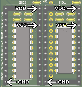
Follow these steps for both sockets:
-
Verify that +5V are available at the VCC pin.
-
Set the VDD jumper at the corresponding SID model block to the top position (6581). Verify that +12V are available at the VDD pin.
-
Set the VDD jumper to the bottom position (8580). Verify that +9V are available at the VDD pin.
If any of these voltages are missing or if they are off by more than 0.5V in either direction it is not safe to insert SID chips into the board. You will have to check your build for mistakes.
If all voltages are correct, power down the C64, remove the VDD jumpers and continue with the next section.
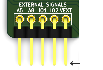
External signals and power supply
The board requires some external signals from the C64-mainboard to support the full range of functions. These signals are feed into the MixSID via the pin header in the lower left:
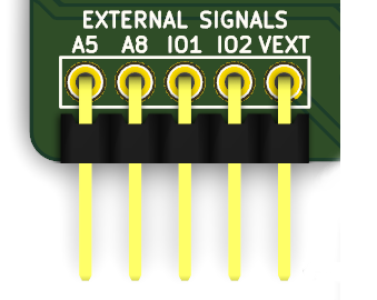
There are different options to access these signals on the C64 mainboard.
The easiest (but least elegant) option is to simply solder a wire directly to the pin of on an IC where the signal is available. Note though that you have to be careful not to apply to much heat to the IC if you do this.
Another option is soldering a wire to the respective IC pin at the bottom side of the board and then route the wire around the mainboard edge and to the MixSID.
Or you can trace the signal on the board until you find a nice via (hole) where the line changes from the bottom to the top side of the mainboard, and solder in a single pin header. This way you can simply use jumper wires to connect the signal to the MixSID pin header.
Address bus signals A5 and A8
The address bus signals A5 and A8 must be connected for the stereo addressing mode to work. They are available (among other locations) at the kernal sockets:
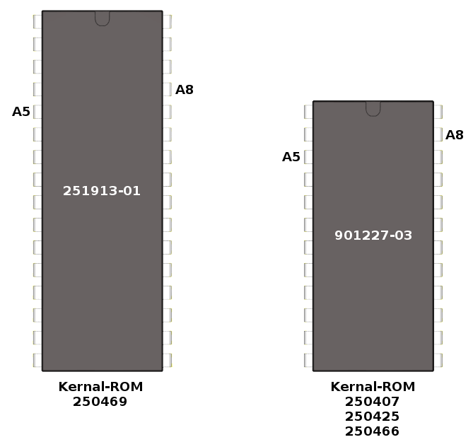
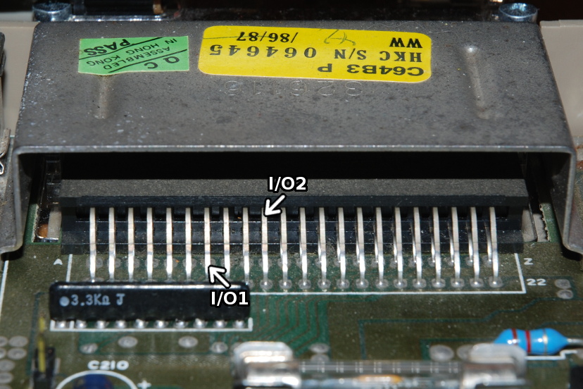
Expansion port signals I/O1 and I/O2
These signals are only required if you want the secondary SID to optionally also appear at $DE00 and/or $DF00 when using stereo addressing mode. See the description of the IO Enable control signals.
If you don’t know whether or not you need this option then you probably don’t.
These signals are available (among other locations) at the expansion port leads on pins 7 and 10:
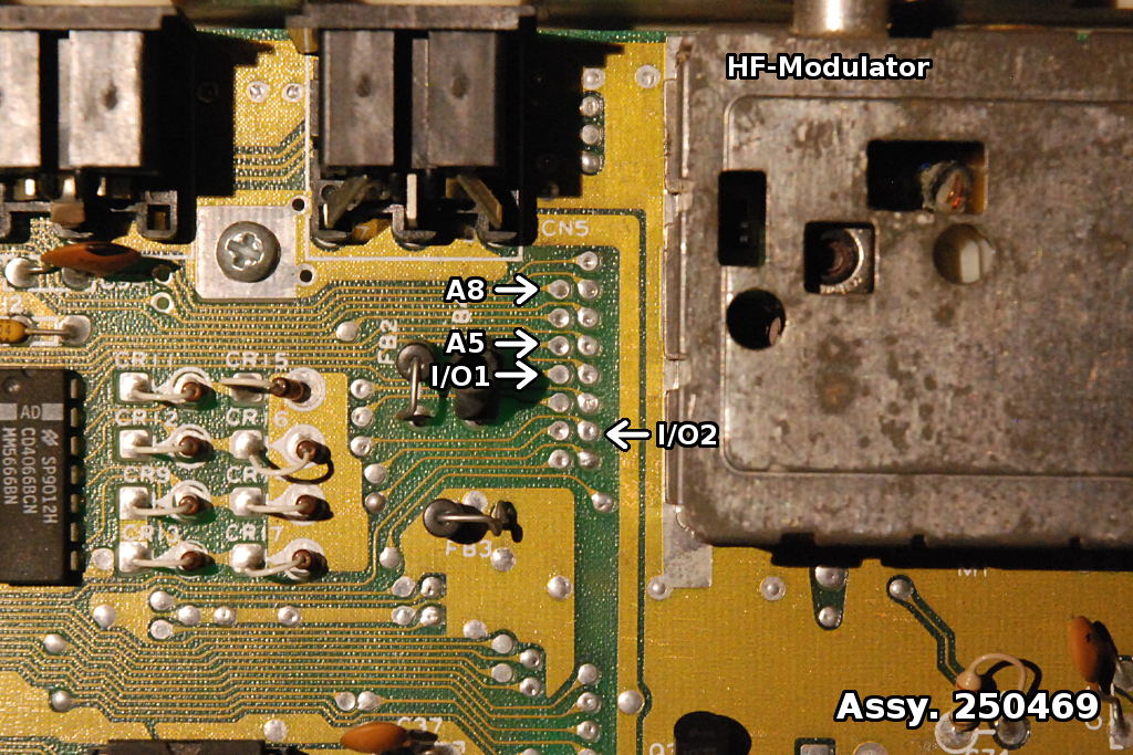
Signal locations on 250469
On the 250469 board, all required signals are available at conveniently placed vias to the left of the HF-Modulator. These vias are placed in a standard 2.54mm raster, so a single pin header might be inserted here.
Power supply on 250469
On a 250469 mainboard, the pin labeled VEXT must be connected to a voltage source of at least +15VDC.
About +20VDC are available the cathode lead of the rectifier diode CR3 on the mainboard and can be safely used for this purpose.
You can either solder a wire at the top side of the mainboard, directly to the cathode lead of CR3, or you can solder a wire from the bottom side of the board.
When choosing to solder to the cathode lead, make sure that it really is the cathode, i.e. the lead close to the ring printed on the diode body, as depicted in the photo below.

From the top

From the bottom
Audio output
Just like the audio output of the C64 mainboard, the audio output of the MixSID board is a line-out signal that must be properly amplified. Connect it to the line input of your stereo system or a headphone amplifier. Do not connect headphones or speakers directly, as low impedance loads such as these will effectively short the output circuit and may possibly destroy it.
Configuration
To ease configuration there is an interactive configuration tool showing how to set
the jumpers for mainboard type, the SID model configuration and the
audio-in options. The effects of the runtime control signals are
demonstrated as well.
Nevertheless, all options and control signals are also described in detail in the following sections.
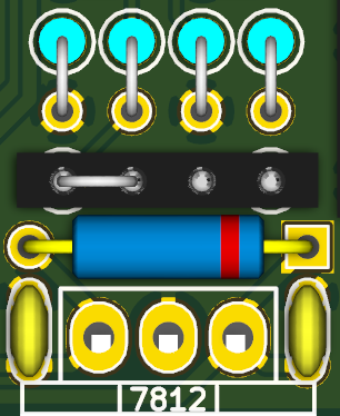
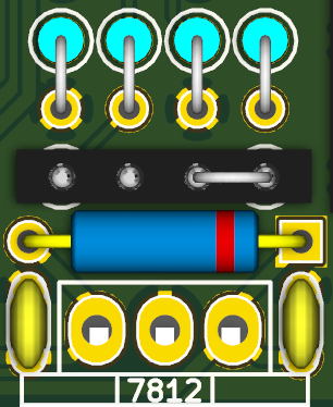
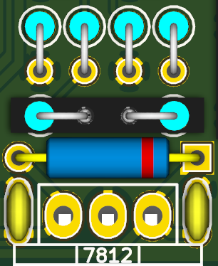
Mainboard Model
The jumper labeled BOARD SELECT must be configured for the correct C64 mainboard model:
 |
 |
| old mainboards 250407, 250425, 250466 (12V, 6581 native) |
new mainboard 250469 (9V, 8580 native) |
On NEW mainboards, a voltage of at least 15V DC must be supplied to the VEXT pin. See Power supply on 25469.
SID Model
Above each SID there are five pin headers that are used to configure the corresponding SID. The first four of these are labeled VDD, FC1, FC2 and R8, and they configure the supply voltage, filter capacitors and output circuit variations:
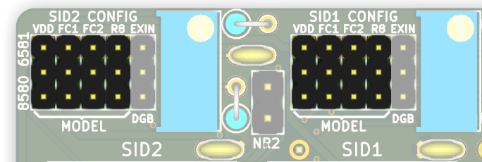
All four jumpers must be set either in the top or bottom position.
In short, place all four jumpers
- in the top position for a 6581.
- in the bottom position for a 8580.
The VDD header routes the supply voltage to the SID. In the top position, +12V are applied. In the bottom position, +9V are applied.
The FC1 and FC2 headers route the SIDs filter capacitor pins to either 470pF capacitors in the top position, or 22nF capacitors in the bottom position.
Finally, the R8 header controls whether or not the output circuit includes an additional 1k resistor to ground immediately at the SID audio output pin. This corresponds to the R8 resistor mentioned in the schematics for the 250469 mainboard. In the top position, R8 is included in the output circuit. In the bottom position, R8 is excluded.
Extin Pin
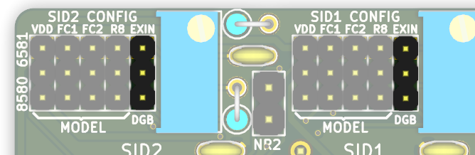
The fifth header labeled EXIN in the SID configuration block routes the SIDs EXTIN Input (Pin 26).
In the top position, EXTIN is routed to an on-board audio input circuit identical to the circuit on the mainboard (100k, 100nF) and ends up at the top pin of the corresponding NR header.
In the bottom position, it is routed to the Digiboost circuit. The following configurations are possible:
Audio input
If the EXIN jumper is set to the top position, the top pin of the corresponding NR header can be used as an audio input in a similar manner as the audio input pin at the A/V connector.
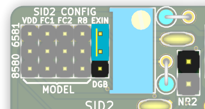
Noise reduction
If the NR pin header is bridged using a jumper, this input is grounded, which is equivalent to the most common noise reduction method of grounding the audio input at the A/V connector. Note though that the effect of this measure may be less noticeable than usual, since there are shorter lines involved to begin with.

Digiboost
If the EXIN jumper is set in the bottom position, the EXTIN pin will be connected to ground via a fixed resistor of 220k and a 1M trimmer in series. This allows safely boosting the volume of digital samples played via $D418 for the 8580, which is usually very quiet. Using the trimmer the balance between samples and regular SID voices can be adjusted.

Extin floating
Finally the EXIN header can also be left open, which is the equivalent of simply bending the EXTIN pin out of the socket. This is sometimes recommended as an alternative noise reduction method, but is also often advised against. I’ve personally found this measure to be of little or no effect.
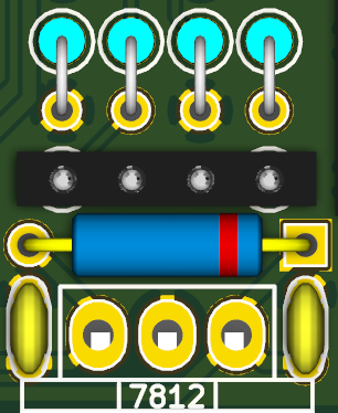
Mainboard audio out routing
You can optionally route audio outputs to the mainboard audio out circuit, so that sound will additionally be available at the mainboard A/V connector and the composite video output.
There are two additional resistor slots on the board, above the diode at the 7812 regulator. On the renderings on this page a 4-pin socket strip is inserted at this spot.
If you leave these slots open, no signal is routed to the mainboards audio output circuit.
If you bridge the left slot, the audio signal of SID2 is used. If you bridge the right slot, the output of SID1 is used.
Never bridge both slots at the same time, as this would pitch both outputs against each other, probably resulting in damage to either SID.
If you want to mix down both signals to mono, you can do so by inserting evenly dimensioned resistors in both slots. 1k or greater is recommended here. Note though that by this measure you will introduce some crosstalk between the audio signals, meaning that the output of SID1 will also be slightly audible in the output of SID2, and vice versa. This will also affect the signals at the board’s own stereo output. So if you want both signals to stay pure you should simply skip this option.
Here’s a summary of the different options:
 |
 |
 |
 |
| no output | SID2 | SID1 | Both mono, 1k resistors |
Runtime Control Signals
All runtime control signals are pulled up to logic HIGH when not connected.
They can either be left unconnected (HIGH) or connected to GND (LOW), or they can be actively driven by another logic IC/microprocessor.
In addition, all signals are applied directly and can freely be changed at runtime without crashing the machine.
The control signals are available at the pin header in the top right corner of the board:
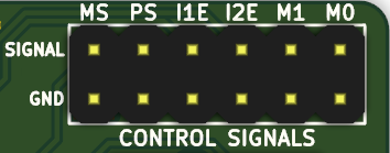
The top row contains the actual signals while all pins on the bottom row are connected to GND.
Mode Select (MS)
The mode select line switches between parallel and stereo addressing mode:
Parallel addressing (HIGH)
This mode should be used when playing back normal SID tunes expecting just one SID at $D400.
Both SIDs are addressed in parallel at $D400 and will thus both play the same tune. The Mixer Control can be used to decide which audio output you wish to listen to.
The secondary SID is forced write-only while the primary SID remains read-write. Thus only the primary SID will respond to read requests to the readable SID registers POTX, POTY, OSC3 and ENV3. This way paddles and mice as well as sound effects based on reading OSC3 or ENV3 will work as usual.
If you install SIDs that differ in sound (either a 8580 and a 6581, or two 6581 with audible differences) and listen to each SID on a different stereo channel while playing a simple mono tune you will notice a stereo effect that results from these differences. Whether or not this sounds good will mostly depend on the tune itself.
Stereo addressing (LOW)
This mode can be used when playing back tunes explicitly created for two SID chips.
When in stereo addressing mode, the primary SID will be addressed at $d400 while the secondary SID will be addressed at both $D420 and $D500 simultaneously. Most stereo tunes expect the second SID at one of these two addresses.
If the IO Enable signals are used, the secondary SID will may additionally be addressed at $DE00 and/or $DF00. While few tunes expect the second SID at these addresses, some hardware extensions want the second SID there.
The Priority Select signal controls which SID is the primary SID at $d400.
In stereo addressing mode the chip select signals (CS1 and CS2) are generated using a combination of the chip select signal for the SID generated by the PLA (CS) and the address bus lines A5 and A8.
CS is asserted by the PLA if the address on the bus is between $D400 and $D7FF.
CS1 is asserted if CS is asserted and neither A5 nor A8 are high (NOR).
CS2 is asserted if CS is asserted and A5 or A8 are high (OR).
In boolean notation:
CS1 = CS . (A5 + A8)
CS2 = CS . (A5 + A8)
Thus the secondary SID does not only appear at the common stereo addresses $D420 and $D500 (which is what matters for this application), but also at a range of other addresses throughout the SID address space:
| Primary Address (CS1) | Secondary Address (CS2) |
|---|---|
| D400 | |
| D420 | |
| D440 | |
| D460 | |
| D480 | |
| D4A0 | |
| D4C0 | |
| D4E0 | |
| D500 | |
| D520 | |
| D540 | |
| D560 | |
| D580 | |
| D5A0 | |
| D5C0 | |
| D5E0 | |
| D600 | |
| D620 | |
| D640 | |
| D660 | |
| D680 | |
| D6A0 | |
| D6C0 | |
| D6E0 | |
| D700 | |
| D720 | |
| D740 | |
| D760 | |
| D780 | |
| D7A0 | |
| D7C0 | |
| D7E0 |
This is implemented in the GAL Logic.
Priority Select (PS)
The priority select signal controls which SID takes the role of primary SID and which SID takes the role of the secondary SID.
The primary SID will always be read-write at $D400. The secondary SID will be write-only at $D400 in parallel addressing mode and read-write at the stereo addresses in stereo addressing mode. See Mode Select for details.
If the signal is HIGH, the SID in the right socket (labeled SID1) will be the primary SID.
If the signal is LOW, the SID in the left socket (labeled SID2) will be the primary SID.
Effects on software SID detection
A common method for detecting the model of the installed SID from within a C64 program involves reading the OSC3 and ENV3 registers.
Since only the primary SID will respond to read requests, the priority selection also controls which SID model is detected by software in a mixed setup.
Effects on paddle accuracy
The POTX and POTY lines will always be routed to the primary SID, which will then measure and report the current paddle position to the software reading the POTX and POTY registers.
The actual values measured by the SID depend on the value of the capacitors externally connected to the POTX and POTY lines. Since different values where used on different mainboards (depending on the SID model usually used on that mainboard), the measurements will be slightly off if a SID model is used as the primary SID that is not native to the board.
For example, when using a 8580 as the primary SID on a 250407 mainboard, the values read from the paddle will be off by about 5%.
However, this hardly matters in practice since the complete range of values can still be reached by turning the paddle knob. This is only a problem if the middle position of the paddle absolutely has to yield a value of 127. In this case, use at least one SID model native to your mainboard and set it to be the primary SID when using paddles.
IO Enable (I1E, I2E)
If the mainboard signals I/O1 or I/O2 are connected to the board, the I1E and I2E signals control whether or not the secondary SID also appears at the corresponding stereo addresses $DE00 or $DF00 when in stereo addressing mode (MS=LOW).
HIGH: Secondary SID does not appear at corresponding IO-Area address
LOW: Secondary SID does appear at corresponding IO-Area address
This feature allows the user to permanently connect the I/O signal lines to the board but still control at runtime whether or not they are used for stereo mode.
Mixer Control (M0, M1)
The M0 and M1 signals choose one of four possible mixer settings:
| M1 | M0 | Left | Right | Type |
|---|---|---|---|---|
| 0 | 0 | SID2 | SID2 | mono |
| 0 | 1 | SID1 | SID1 | mono |
| 1 | 0 | SID1 | SID2 | stereo |
| 1 | 1 | SID2 | SID1 | stereo |
Thus if both signals are not connected, the output of the SID in the left socket is routed to the left audio channel and the output of the SID in the right socket is routed to the right audio channel.
Schematics

License
                      MixSID Hardware and Firmware
     Copyright (c) 2016, Henning Bekel <h.bekel@googlemail.com>

                    GNU GENERAL PUBLIC LICENSE
                       Version 2, June 1991

 Copyright (C) 1989, 1991 Free Software Foundation, Inc.
               59 Temple Place, Suite 330, Boston, MA  02111-1307  USA
 Everyone is permitted to copy and distribute verbatim copies
 of this license document, but changing it is not allowed.

                            Preamble

  The licenses for most software are designed to take away your
freedom to share and change it.  By contrast, the GNU General Public
License is intended to guarantee your freedom to share and change free
software--to make sure the software is free for all its users.  This
General Public License applies to most of the Free Software
Foundation's software and to any other program whose authors commit to
using it.  (Some other Free Software Foundation software is covered by
the GNU Library General Public License instead.)  You can apply it to
your programs, too.

  When we speak of free software, we are referring to freedom, not
price.  Our General Public Licenses are designed to make sure that you
have the freedom to distribute copies of free software (and charge for
this service if you wish), that you receive source code or can get it
if you want it, that you can change the software or use pieces of it
in new free programs; and that you know you can do these things.

  To protect your rights, we need to make restrictions that forbid
anyone to deny you these rights or to ask you to surrender the rights.
These restrictions translate to certain responsibilities for you if you
distribute copies of the software, or if you modify it.

  For example, if you distribute copies of such a program, whether
gratis or for a fee, you must give the recipients all the rights that
you have.  You must make sure that they, too, receive or can get the
source code.  And you must show them these terms so they know their
rights.

  We protect your rights with two steps: (1) copyright the software, and
(2) offer you this license which gives you legal permission to copy,
distribute and/or modify the software.

  Also, for each author's protection and ours, we want to make certain
that everyone understands that there is no warranty for this free
software.  If the software is modified by someone else and passed on, we
want its recipients to know that what they have is not the original, so
that any problems introduced by others will not reflect on the original
authors' reputations.

  Finally, any free program is threatened constantly by software
patents.  We wish to avoid the danger that redistributors of a free
program will individually obtain patent licenses, in effect making the
program proprietary.  To prevent this, we have made it clear that any
patent must be licensed for everyone's free use or not licensed at all.

  The precise terms and conditions for copying, distribution and
modification follow.

                    GNU GENERAL PUBLIC LICENSE
   TERMS AND CONDITIONS FOR COPYING, DISTRIBUTION AND MODIFICATION

  0. This License applies to any program or other work which contains
a notice placed by the copyright holder saying it may be distributed
under the terms of this General Public License.  The "Program", below,
refers to any such program or work, and a "work based on the Program"
means either the Program or any derivative work under copyright law:
that is to say, a work containing the Program or a portion of it,
either verbatim or with modifications and/or translated into another
language.  (Hereinafter, translation is included without limitation in
the term "modification".)  Each licensee is addressed as "you".

Activities other than copying, distribution and modification are not
covered by this License; they are outside its scope.  The act of
running the Program is not restricted, and the output from the Program
is covered only if its contents constitute a work based on the
Program (independent of having been made by running the Program).
Whether that is true depends on what the Program does.

  1. You may copy and distribute verbatim copies of the Program's
source code as you receive it, in any medium, provided that you
conspicuously and appropriately publish on each copy an appropriate
copyright notice and disclaimer of warranty; keep intact all the
notices that refer to this License and to the absence of any warranty;
and give any other recipients of the Program a copy of this License
along with the Program.

You may charge a fee for the physical act of transferring a copy, and
you may at your option offer warranty protection in exchange for a fee.

  2. You may modify your copy or copies of the Program or any portion
of it, thus forming a work based on the Program, and copy and
distribute such modifications or work under the terms of Section 1
above, provided that you also meet all of these conditions:

    a) You must cause the modified files to carry prominent notices
    stating that you changed the files and the date of any change.

    b) You must cause any work that you distribute or publish, that in
    whole or in part contains or is derived from the Program or any
    part thereof, to be licensed as a whole at no charge to all third
    parties under the terms of this License.

    c) If the modified program normally reads commands interactively
    when run, you must cause it, when started running for such
    interactive use in the most ordinary way, to print or display an
    announcement including an appropriate copyright notice and a
    notice that there is no warranty (or else, saying that you provide
    a warranty) and that users may redistribute the program under
    these conditions, and telling the user how to view a copy of this
    License.  (Exception: if the Program itself is interactive but
    does not normally print such an announcement, your work based on
    the Program is not required to print an announcement.)

These requirements apply to the modified work as a whole.  If
identifiable sections of that work are not derived from the Program,
and can be reasonably considered independent and separate works in
themselves, then this License, and its terms, do not apply to those
sections when you distribute them as separate works.  But when you
distribute the same sections as part of a whole which is a work based
on the Program, the distribution of the whole must be on the terms of
this License, whose permissions for other licensees extend to the
entire whole, and thus to each and every part regardless of who wrote it.

Thus, it is not the intent of this section to claim rights or contest
your rights to work written entirely by you; rather, the intent is to
exercise the right to control the distribution of derivative or
collective works based on the Program.

In addition, mere aggregation of another work not based on the Program
with the Program (or with a work based on the Program) on a volume of
a storage or distribution medium does not bring the other work under
the scope of this License.

  3. You may copy and distribute the Program (or a work based on it,
under Section 2) in object code or executable form under the terms of
Sections 1 and 2 above provided that you also do one of the following:

    a) Accompany it with the complete corresponding machine-readable
    source code, which must be distributed under the terms of Sections
    1 and 2 above on a medium customarily used for software interchange; or,

    b) Accompany it with a written offer, valid for at least three
    years, to give any third party, for a charge no more than your
    cost of physically performing source distribution, a complete
    machine-readable copy of the corresponding source code, to be
    distributed under the terms of Sections 1 and 2 above on a medium
    customarily used for software interchange; or,

    c) Accompany it with the information you received as to the offer
    to distribute corresponding source code.  (This alternative is
    allowed only for noncommercial distribution and only if you
    received the program in object code or executable form with such
    an offer, in accord with Subsection b above.)

The source code for a work means the preferred form of the work for
making modifications to it.  For an executable work, complete source
code means all the source code for all modules it contains, plus any
associated interface definition files, plus the scripts used to
control compilation and installation of the executable.  However, as a
special exception, the source code distributed need not include
anything that is normally distributed (in either source or binary
form) with the major components (compiler, kernel, and so on) of the
operating system on which the executable runs, unless that component
itself accompanies the executable.

If distribution of executable or object code is made by offering
access to copy from a designated place, then offering equivalent
access to copy the source code from the same place counts as
distribution of the source code, even though third parties are not
compelled to copy the source along with the object code.

  4. You may not copy, modify, sublicense, or distribute the Program
except as expressly provided under this License.  Any attempt
otherwise to copy, modify, sublicense or distribute the Program is
void, and will automatically terminate your rights under this License.
However, parties who have received copies, or rights, from you under
this License will not have their licenses terminated so long as such
parties remain in full compliance.

  5. You are not required to accept this License, since you have not
signed it.  However, nothing else grants you permission to modify or
distribute the Program or its derivative works.  These actions are
prohibited by law if you do not accept this License.  Therefore, by
modifying or distributing the Program (or any work based on the
Program), you indicate your acceptance of this License to do so, and
all its terms and conditions for copying, distributing or modifying
the Program or works based on it.

  6. Each time you redistribute the Program (or any work based on the
Program), the recipient automatically receives a license from the
original licensor to copy, distribute or modify the Program subject to
these terms and conditions.  You may not impose any further
restrictions on the recipients' exercise of the rights granted herein.
You are not responsible for enforcing compliance by third parties to
this License.

  7. If, as a consequence of a court judgment or allegation of patent
infringement or for any other reason (not limited to patent issues),
conditions are imposed on you (whether by court order, agreement or
otherwise) that contradict the conditions of this License, they do not
excuse you from the conditions of this License.  If you cannot
distribute so as to satisfy simultaneously your obligations under this
License and any other pertinent obligations, then as a consequence you
may not distribute the Program at all.  For example, if a patent
license would not permit royalty-free redistribution of the Program by
all those who receive copies directly or indirectly through you, then
the only way you could satisfy both it and this License would be to
refrain entirely from distribution of the Program.

If any portion of this section is held invalid or unenforceable under
any particular circumstance, the balance of the section is intended to
apply and the section as a whole is intended to apply in other
circumstances.

It is not the purpose of this section to induce you to infringe any
patents or other property right claims or to contest validity of any
such claims; this section has the sole purpose of protecting the
integrity of the free software distribution system, which is
implemented by public license practices.  Many people have made
generous contributions to the wide range of software distributed
through that system in reliance on consistent application of that
system; it is up to the author/donor to decide if he or she is willing
to distribute software through any other system and a licensee cannot
impose that choice.

This section is intended to make thoroughly clear what is believed to
be a consequence of the rest of this License.

  8. If the distribution and/or use of the Program is restricted in
certain countries either by patents or by copyrighted interfaces, the
original copyright holder who places the Program under this License
may add an explicit geographical distribution limitation excluding
those countries, so that distribution is permitted only in or among
countries not thus excluded.  In such case, this License incorporates
the limitation as if written in the body of this License.

  9. The Free Software Foundation may publish revised and/or new versions
of the General Public License from time to time.  Such new versions will
be similar in spirit to the present version, but may differ in detail to
address new problems or concerns.

Each version is given a distinguishing version number.  If the Program
specifies a version number of this License which applies to it and "any
later version", you have the option of following the terms and conditions
either of that version or of any later version published by the Free
Software Foundation.  If the Program does not specify a version number of
this License, you may choose any version ever published by the Free Software
Foundation.

  10. If you wish to incorporate parts of the Program into other free
programs whose distribution conditions are different, write to the author
to ask for permission.  For software which is copyrighted by the Free
Software Foundation, write to the Free Software Foundation; we sometimes
make exceptions for this.  Our decision will be guided by the two goals
of preserving the free status of all derivatives of our free software and
of promoting the sharing and reuse of software generally.

                            NO WARRANTY

  11. BECAUSE THE PROGRAM IS LICENSED FREE OF CHARGE, THERE IS NO WARRANTY
FOR THE PROGRAM, TO THE EXTENT PERMITTED BY APPLICABLE LAW.  EXCEPT WHEN
OTHERWISE STATED IN WRITING THE COPYRIGHT HOLDERS AND/OR OTHER PARTIES
PROVIDE THE PROGRAM "AS IS" WITHOUT WARRANTY OF ANY KIND, EITHER EXPRESSED
OR IMPLIED, INCLUDING, BUT NOT LIMITED TO, THE IMPLIED WARRANTIES OF
MERCHANTABILITY AND FITNESS FOR A PARTICULAR PURPOSE.  THE ENTIRE RISK AS
TO THE QUALITY AND PERFORMANCE OF THE PROGRAM IS WITH YOU.  SHOULD THE
PROGRAM PROVE DEFECTIVE, YOU ASSUME THE COST OF ALL NECESSARY SERVICING,
REPAIR OR CORRECTION.

  12. IN NO EVENT UNLESS REQUIRED BY APPLICABLE LAW OR AGREED TO IN WRITING
WILL ANY COPYRIGHT HOLDER, OR ANY OTHER PARTY WHO MAY MODIFY AND/OR
REDISTRIBUTE THE PROGRAM AS PERMITTED ABOVE, BE LIABLE TO YOU FOR DAMAGES,
INCLUDING ANY GENERAL, SPECIAL, INCIDENTAL OR CONSEQUENTIAL DAMAGES ARISING
OUT OF THE USE OR INABILITY TO USE THE PROGRAM (INCLUDING BUT NOT LIMITED
TO LOSS OF DATA OR DATA BEING RENDERED INACCURATE OR LOSSES SUSTAINED BY
YOU OR THIRD PARTIES OR A FAILURE OF THE PROGRAM TO OPERATE WITH ANY OTHER
PROGRAMS), EVEN IF SUCH HOLDER OR OTHER PARTY HAS BEEN ADVISED OF THE
POSSIBILITY OF SUCH DAMAGES.

                     END OF TERMS AND CONDITIONS